Controllable Circuits
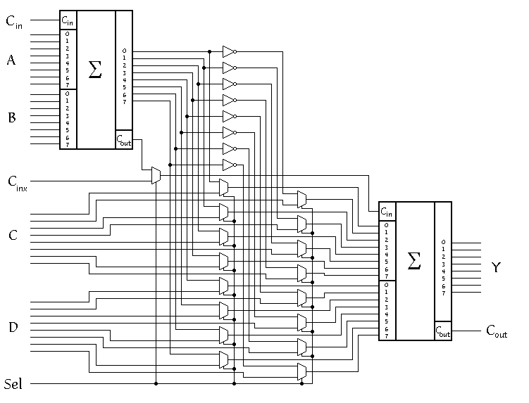
The controllable circuit is designed so that the connection lines in between of the two adders are made controllable by wiring out them to nine input pins: Cinx, C (c0 - c7), D (d0 - d7). An additinal input pin Sel is added to select between the normal circuit operation mode and the test mode. You will find the circuit under the name controllable.agm.
