|
|
|
FAULT MODELING AND SIMULATION
Logical faults represent
the effect of physical faults on the behavior of the system.
Why we model physical faults as logical ones:
Structural fault models assume that components are fault-free and only their interconnections are affected:
1.2. Fault Detection and Redundancy
1.2.1.
Fault detection in combinational circuits
1.2.2. Detectability of
faults
1.2.3.
Redundancy
1.2.1. Fault Detection in Combinational Circuits
Circuit: Let Z(x) be the logic function of a circuit N, where x represents an arbitrary input vector and Z(x) denotes the mapping realized by N.
Faulty circuit: The presence of a fault f transforms N into a new circuit Nf with a new function Zf (x).
Test: Denote by t
a specific input vector (test vector), and by Z(t)
the response of N. Let us call a sequence of test vectors by test:
T={t1 t2 ... tn }.
The circuit is tested by
applying a test T and by comparing the output response with the expected
output response of N, ![]() .
.
Fault detection:
A test vector t detects a fault f iff![]() .
.
Fault sensitization:
A line in a circuit whose value in the test t changes in the presence
of the fault f is said to be sensitized to the fault f by
the test t. We say also: the test t activates
a fault f. A path composed of sensitized lines is called a sensitized
path.
We say also: the test t propagates a fault (fault
effect) along sensitized path.
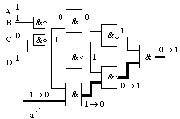
Example:
1. In Figure a fault a/0 is sensitized by the value 1 on a line a.
2. A test t = 1101
is simulated, both without and with the fault a/0. The results of the simulation
are different in the two cases, shown in a form ![]() where
where ![]() and
and ![]() are corresponding signal values in the fault-free and in the faulty circuit.
The fault is detected since the output values in the two cases are different.
A path from the faulty line a is sensitized (bold lines) to the primary
output of the circuit.
are corresponding signal values in the fault-free and in the faulty circuit.
The fault is detected since the output values in the two cases are different.
A path from the faulty line a is sensitized (bold lines) to the primary
output of the circuit.
1.2.2. Detectability of Faults
A fault f is detectable if there exists a test t that detects f , otherwise, f is an undetectable fault.
For an undetectable fault
f , ![]() ,
and no test can simultaneously activate f and create a sensitized
path to a primary output.
,
and no test can simultaneously activate f and create a sensitized
path to a primary output.
Note: The presence of an undetectable fault f may prevent the detection of another fault g , even then when there exists a test which detects the fault g.
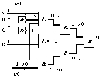
Example: In Figure, the fault b/1 is undetectable. As we saw in the previous example, the test t = 1101 detects the fault a/0. However, in the presents of b/1, the test t is not any more able to detect the fault a/0.
A combinational circuit that contains an undetectable stuck fault is said to be redundant, since such a circuit can always be simplified by removing at least one gate or gate input:
|
|
|
| AND (NAND) input s-a-1 AND (NAND) input s-a-0 OR (NOR) input s-a-0 OR (NOR) input s-a-1 |
Remove input Remove gate, replace by 0 (1) Remove input Remove gate, replace by 1 (0) |
A combinational circuit in which all stuck faults are detectable is said to be irredundant.
Redundancy may be introduced on purpose in the following cases:
1.3.1.
Fault equivalence classes
1.3.2.
Equivalence fault collapsing
1.3.3.
Fault location
1.3.1. Fault Equivalence Classes
Two faults f and
g are said to be functionally equivalent iff ![]() .
.
A test t is said
to distinguish between two faults f and g if ![]() ;
such faults are distinguishable. There is no test that can distinguish between
two functionally equivalent faults.
;
such faults are distinguishable. There is no test that can distinguish between
two functionally equivalent faults.
The relation of functional
equivalence partitions the set of all possible faults into functional equivalence
classes. For fault analysis it is sufficient to consider only one representative
fault from every equivalence class.
1.3.2. Equivalence Fault Collapsing
With any n-input gate we can associate 2(n + 1) single stuck faults. For a NAND gate all the input s-a-0 faults and the output s-a-1 are functionally equivalent.
In general, for a gate with
controlling value c and inversion i , all the input s-a-c
faults and the output ![]() are functionally equivalent. Thus for an n-input gate (n>1) we
need to consider only n+2 single stuck faults.
are functionally equivalent. Thus for an n-input gate (n>1) we
need to consider only n+2 single stuck faults.
This type of reduction of
the set of faults to be analyzed based on equivalence relations is called equivalence
fault collapsing.
If in addition to fault detection, the goal of testing is fault location as well, we need to apply a test that not only detects the detectable faults but also distinguishes among them as much as possible. A complete location test distinguishes between every pair of distinguishable faults in a circuit.
The presence of an undetectable fault may invalidate a complete location test. If f and g are two distinguishable faults, they may become functionally equivalent in the presence of an undetectable fault.
A complete location test can diagnose a fault to within a functional equivalence class. This is the maximal diagnostic resolution that can be achieved.
Two faults f and
g are functionally equivalent under a test T iff ![]() for every test vector
for every test vector ![]() .
.
Functional equivalence implies equivalence under any test but equivalence under a given test does not imply functional equivalence.
If the objective of a testing is limited to fault detection only, then in addition to fault equivalence, another fault relation can be used to reduce the number of faults that must be considered.
Definition. Let Tg be the set of all test vectors that detect a fault g. A fault f dominates the fault g iff f and g are functionally equivalent under Tg.
If f dominates g , then any test t that detects g will also detect f. Therefore, for fault detection it is unnecessary to consider the dominating fault f , since by deriving a test for g we automatically obtain a test that detects f as well.
Single stuck-fault model (SSF) is the classical or standard fault model. Its usefulness results from the following attributes:
1.6.1.
The number of multiple faults
1.6.2. Fault masking
1.6.3. Circular fault masking
1.6.1. The Number of Multiple Faults
Multiple stuck-fault (MSF) model is a straightforward extension of the SSF model in which several lines can be simultaneously stuck.
If n - is the number of possible
SSF sites, there are 2n possible SSFs, but there are ![]() possible MSFs.
possible MSFs.
If we assume that the multiplicity of faults is no greater than k , then the number of possible MSFs is
![]() .
.
The number of multiple faults is very big. However, their consideration is needed because of possible fault masking.
Definition. Let Tg be the test that detects a fault g . We say that a fault f functionally masks the fault g iff the multiple fault { f, g } is not detected by any test in Tg .
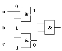
Example: In Figure the test 011 is the only test that detects the fault c/0. The same test does not detect the multiple fault { c/0, a/1}. Thus a/1 masks c/0.
Definition.
Let ![]() be the set of all tests in T that detect a fault g. A fault f
masks the fault g under a test T iff the multiple
fault { f , g } is not detected by any test in Tg.
be the set of all tests in T that detect a fault g. A fault f
masks the fault g under a test T iff the multiple
fault { f , g } is not detected by any test in Tg.
Functional masking implies masking under any test, but the converse statement is not always true.
Multiple fault F may be not detected by a complete test T for single faults because of circular masking relations under T among the components of F.
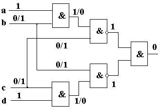
Example: The test T = {1111, 0111, 1110, 1001, 1010, 0101} detects every SSF in the circuit in Figure. Let f be b/1 and g be c/1. The only test in T that detects the single faults f and g is 1001. However, the multiple fault { f , g } is not detected because under the test vector 1001, f masks g and g masks f .
|
|