|
|
|
TEST GENERATION
Test generation (TG) is
a complex problem with many interacting aspects e.g. the cost of TG (complexity
of the method, test length) and the quality of generated tests (fault
coverage).
Test generation can be produced at different levels: gate-level, macro-level
and functional level. There are also different methods used in test generation:
deterministic methods (fault-oriented TG, fault independent TG),
random TG, combined deterministic/random TG, a.o.
2.Gate-
Level Fault- Oriented Test Generation
The complexity of TG methods and algorithms depends on the structure of the
gate-level circuits. Consider the following structures:
2.1.
Fanout- Free Circuits
Three fundamental steps are used in generating a test for a fault l s-a-v:
2.1.1.
Fault activation
2.1.2. Fault propagation
2.1.3.
Line justification
2.1.1.
Fault Activation
To activate a fault on a line l in a circuit means to assign a value to a line
l (and may be some additional values to some other lines) so that the value
of a line l is changed to the opposite value in the case of presence of the
fault.
Example:
To activate a fault stuck-at-1 (s-a-1) on the line 9 of the circuit we have
to assign to the line 9 the value 0. In the case of the fault s-a-1 the value
0 on that line will change to 1.
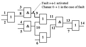
On the other hand, to activate the AND-type bridging fault b(9,10) between lines 9 and 10, we have to assign the value 1 to the line 9 and the value 0 to the line 10 (or as the second option, the value 0 to the line 9 and the value 1 to the line 10). In the case of this fault, the value 1 on the line 9 will change to 0 (or the value 1 on the line 10 will change to 0 for the second option).
2.1.2.
Fault Propagation
Example:
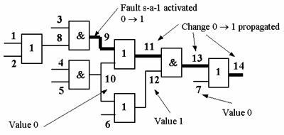
To propagate the error signal of a fault stuck-at-1 (s-a-1) on the line 9 through
the OR-gate 11 we have to assign value
0 to the line 10. In the case of the fault s-a-1
on the line 9 the value 0 on the line 11 will change to 1.
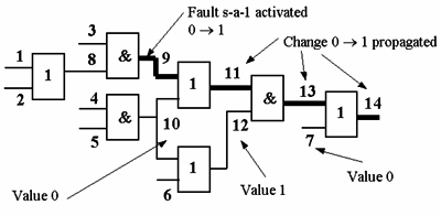
Further, to propagate the erroneous signal from the line 11 to the primary output 14, we have to assign the values 1 and 0 to lines 12 and 7, correspondingly. In the case of the fault s-a-1 on the line 9, the value 0 on the line 14 will change to 1.
Example:
To justify the value 0 on the line 9, we have to assign 0 either to the line
3 or to the line 8 or to both lines.
|
|
|